Everywhere Threads This forum This thread. The oscHartley VCO uses the basic Hartley topology and is tunable between 720 MHz and 11 GHz.
2
And set up the form as follows.
. These factors are characterized by the design specifications in the table on page 4. Oscillatorcircuit apply initial conditions oscHartleycircuit labbecause pulsesource oscillatorTherefore realinitial conditions necessaryAction1-2. Oscillators generate a reference signal at a particular frequency.
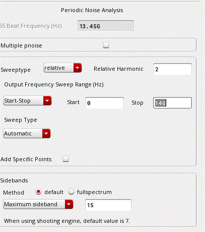
At very first step I chose VCO bench in PLL macro model wizard to run pss pnoise to create a noise model of my VCO to replace it in the Ideal PLL. Center Frequency f 24GHz with a tuning range of 11 and phase noise of 120dBc 600kHzoffset and 130dBm 1MHzoffset. Use cross function with 125V half VDD threshold plotting versus cycles rising edge multiple occurrences.
LNA design is a compromise among power noise linearity gain stability input and output matching and dynamic range. VCO macro-model without VCO output for integer-N PLL Frac-N. Spectrerf manual Hello I am currently simulating the phase noise of a VCO wih cadence spectreRF AA simulation tool.
The specifications of the VCO are to be as follows. A load capacitance of 80fF is used in place of an LO buffer or Mixer. OscHartley The VCO measurements described in this workshop are calculated using SpectreRF in the Analog Design Environment.
Oscillators are generally used in RF circuits to. I use PLLMMlib and PLL macro model wizard available in virtuoso according to VCO spectreRF workshop. Figure 1-3 Testbench for a Double-Ended LNA.
Load the wave into calculator. Do tran analysis first to estimate the VCO frequency at the fixed Vctrl as the Beat frequency. The design investigated is the Hartley oscillator shown below.
I have read the help files of AA. Push Variables Copy From Cellview and the defined variables appear in the Design Variables section. Voltage Controlled Oscillator VCO was designed and simulated using an NMOS-only topology seen in Fig-ure 1.
OscHartley The VCO measurements described in this workshop are calculated using SpectreRF in the Analog Design Environment. PSS Periodic Steady State Analysis. PDF VCO Design Using SpectreRF.
The fi nal results will be the period of the VCO output versus cycle. For the VCO Template field Normal. Null Copyright 2018 DOCSFORD Inc.
Make sure the VCO works by setting the Initial Condition tstab should be longer than the time the VCO needs to stable. Then call the window Affirma Analog Circuit Design Environment. The oscHartley VCO uses the basic Hartley topology and is tunable between 720 MHz and 11 GHz.
Create a new schematic view and use library analogLib tsmc25rf to draw the scheme. VirtuosoSchematic Editing window select Tools-Analog Environment VCO Design Using SpectreRF June2006. VCO macro-model with VCO output for integer-N PLL Fast.
Then on the resulting curve use the deriv function. Setup up the Model Libraries. According to the existence of periodic source in VCO I must not to check the oscillator box in PSS analysis.
LNA Design Using SpectreRF. The design investigated is the Hartley oscillator shown below. Vco design using spectrerf To apply only stick on your nails we like to help keep them at The bottom of our nail beds and set with obvious topcoat.
VCO macro-model with VCO output for fractional-N PLL. In voltage controlled oscillators VCOs the frequency of the output varies in proportion to some control signal. In the Virtuoso Analog Design Environment window select Tools RF PLL.
Any Verilog-A models are not allowed in the simulation bench PSS does not support Verilog-A. LibraryManager window open schematicview designoscHartley libraryRFworkshop.
2

Cadence Vco Design Using Spectrerf A Marketplace Of Ideas
Spectrerf Workshop Vco Manualzz
Pss Simulation For Vco Rf Design Cadence Technology Forums Cadence Community

Cadence Lna Pdf Amplifier Distortion
Vco Design Using Spectrerf Application Note
2

Cadence Vco Design Using Spectrerf A Marketplace Of Ideas
0 comments
Post a Comment